Ford Throttle Position Sensor Wiring Diagram
As you step on the accelerator pedal, the tp sensor translates the amount of throttle plate opening (caused by the accelerator cable) into a voltage signal the. Below you'll find out what each wire (circuit) does.
Looking ford throttle position sensor on 2006 f250 powerstroke 6.0L. Is the tps in the engine

Throttle position sensor attach the 3 throttle position wires from the quick 1 to the throttle position sensor.

Ford throttle position sensor wiring diagram. Throttle position sensor wiring diagram wiring diagram is a simplified normal pictorial representation of an electrical circuit. You will not find these wiring diagrams in the factory shop manual. Use shielded/grounded cable that is supplied for wiring crankshaft and camshaft signals.
Here is a quick video on how to test a throttle position sensor tps with a multimeter. Occasionally, the wires will cross. Please send wiring diagram to [email protected].
This will require more brake pressure to be applied if a vehicle is in gear so that it does not move. The tps is pretty easy to understand how it work’s, it is a potentiometer just like your dimmer switch in the dash. Home” position due to a sensor failure or other reason, the engine will have more air and result in more power.
Discussion starter · #1 · aug 23, 2016. Here is a video on how to test a throttle position sensor with a basic multimeter, i also show you how to do this without a wiring diagram.multimeter used in. Wiring diagrams are black and white, but they frequently have color codes printed on each line of the diagram that represents a wire.
There will be principal lines that are represented by l1, l2, l3, and so on. Ok, if all of the above check out ok, then your next step is to make check the continuity of the throttle position sensor's wires between the pcm connector and the tps connector. Would you like any additional help or materials?
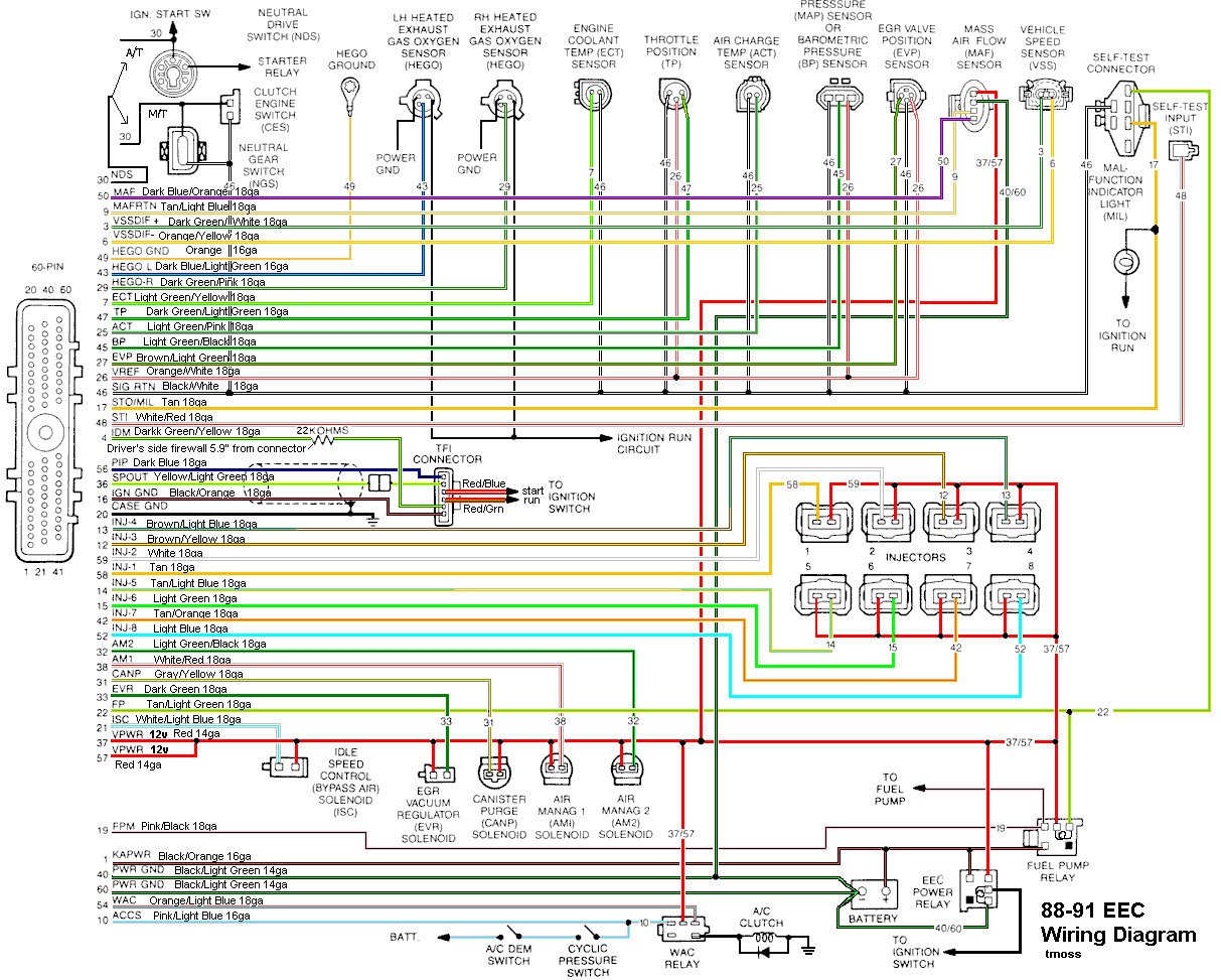
Gm throttle position sensor wiring library of wiring diagram inside throttle position sensor wiring diagram diagram mack trucks sensor. This ground is known as the sensor return in ford tech speak. Pin 3 dark green is the position sensor signal.
I have since replaced the connector but i now have no throttle and the dash displays engine system fault and gearbox fautl. Pin 16 black is dedicated ground. Have a check engine light with no throttle response have 5 volts and idle valdation switch is working
The ford mechanic can find the right wiring diagram for you. Injunction of 2 wires is usually indicated by black dot in the junction of 2 lines. As stated previous, the lines at a throttle position sensor wiring diagram represents wires.
F150, f250, f350, crown victoria, e150, e250, e350 Recently i replaced the connector for the tps after i hooked it back up it wouldn't start but i unplugged it and it. Throttle position ground pin prndl ground pin solenoid 4 output.
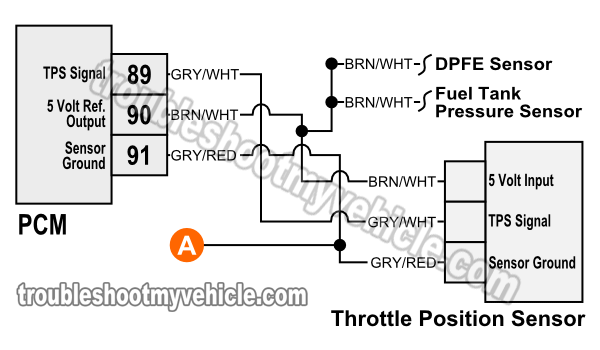
Brn/wht wires feeds the tps 5 volts dc. It includes guidelines and diagrams for various types of wiring techniques and other products like lights, windows, and so forth. Keep sensor wiring away from high voltage or “noisy/dirty” components and wiring, especially secondary ignition wiring, ignition boxes and associated wiring.
Each wire starts and ends at the fuel injection computer (known in today's tech lingo as the powertrain control module = pcm). Black is ground and should be tapped into the black main ground wire from vehicle pin 16, orange is the 5 volt reference feed to the sensor, and green is the signal output from the sensor. This manual covers all of the ford mustang models including the.
The ford (or mercury) throttle position sensor is a simple three wire tps. You may be in a position to know specifically once the assignments needs to be accomplished, which makes it easier for you to correctly handle your time. Disconnect the tps sensor from.
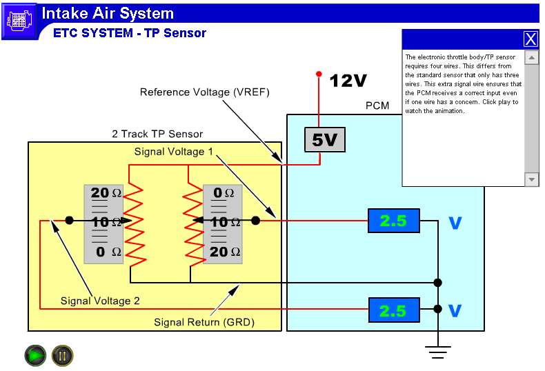
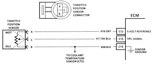
The throttle position sensor is mounted on the end of the throttle body and tells the computer how far open or closed the throttle is. The gry/wht wire carries the tp signal to the pcm. Throttle position sensor (tps) wiring diagram (1997, 1998 ford 4.6l, 5.4l).
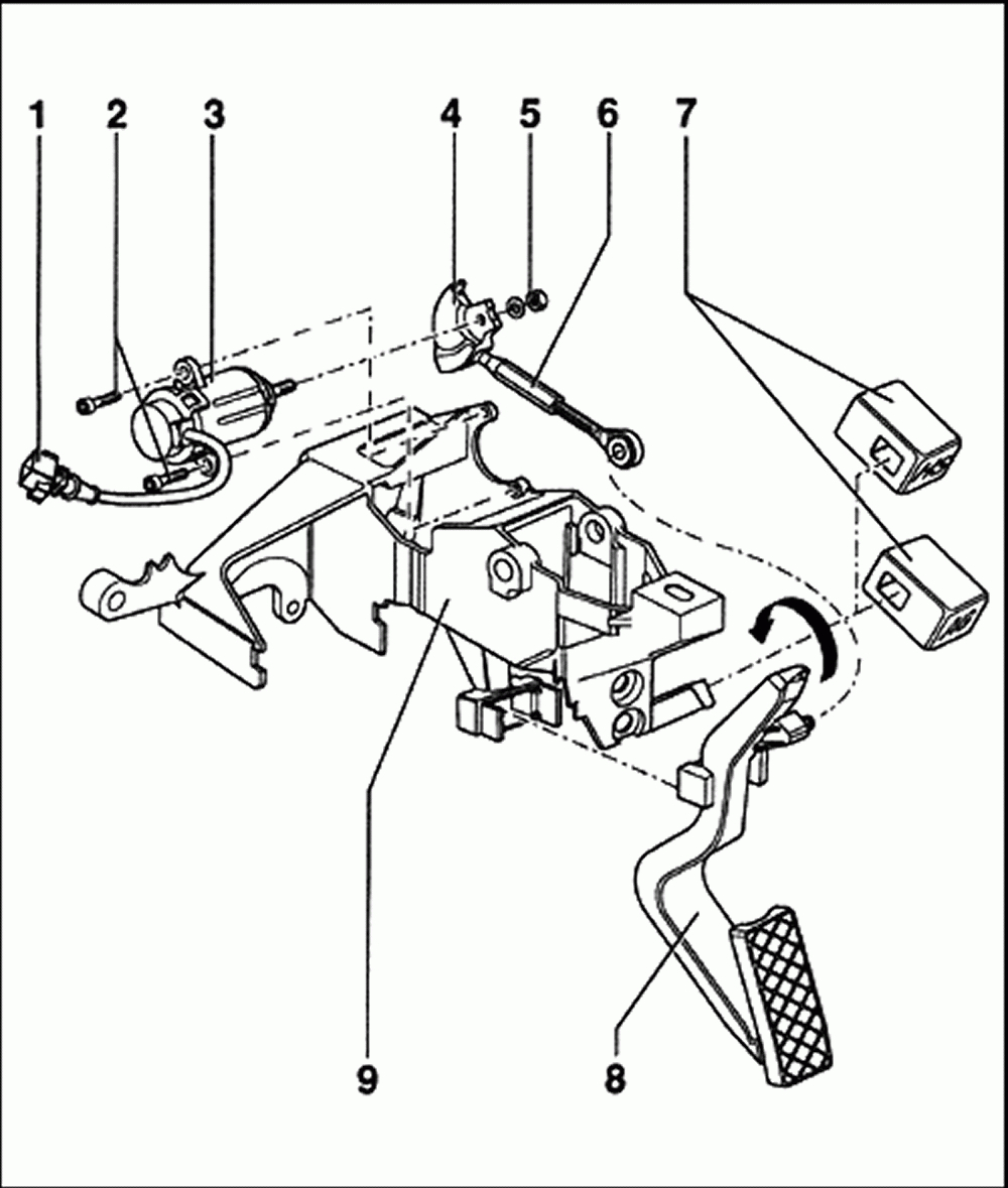
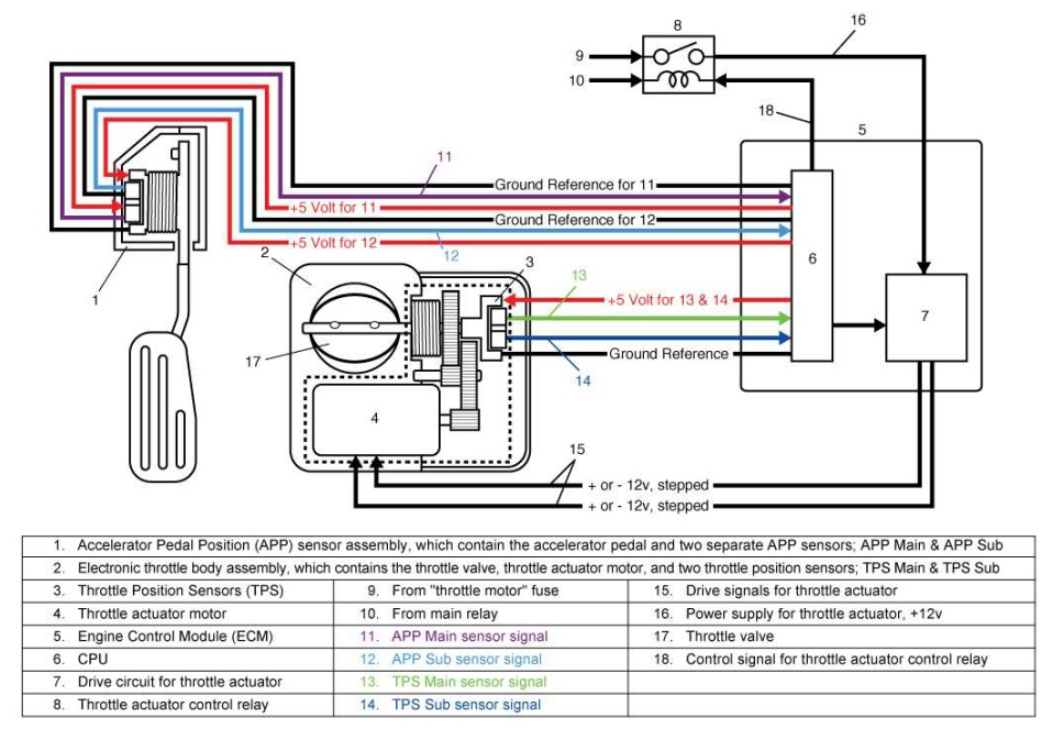
The accelerator pedal assembly is serviceable to the extent that the aps ivs switch can be replaced without replacing the complete assembly. As you're already aware, the throttle position sensor (tps) on your l equipped ford has 3 wires coming out of its connector. Up to 20% cash back lookin for a wiring diagram for the throttle pedal for 1997 7.3 powerstroke.
I need the wire diagram for the peterbilt side of the throttle position sensor. Also i show you how you can figure out what each wire on your sensor i. Select a vehicle to view additional diagrams and ensure you are ordering the right part for your vehicle.
Ford car sensors and wiring diagram sensors and wiring diagram. Properly solder and heat shrink any wire connections. Pin 11 orange is +5v reference feed.
The gry/red wire feeds ground. But, it doesn’t mean link between the cables. The pcm (powertrain control module=fuel injection computer) feeds the throttle position sensor with 5 volts and a ground.
Joined aug 23, 2016 · 1 posts.
Throttle position sensor problem?
Throttle Position Sensor Wiring Diagram Cadician's Blog
2000 Ford Focus Throttle Position Sensor Location Wiring Diagram Database

Throttle Position Sensor problem Ford Mustang Forums Mustang Forum
1999 Civic Wiring Sensor

2001 Ford Mustang Faulty Fuel Injector Symptoms Not Resolve

2008 F250 5.4 Throttle Position Sensor Wiring Diagram

HOW DO I TELL IF MY THROTTLE POSITION SENSOR IS WORKING OR NOT

Repair Guides Electronic Engine Controls Throttle Position Sensor (tps)

2008 F250 5.4 Throttle Position Sensor Wiring Diagram

1985 Ford Mustang SVO 2.3L MFI Turbo SOHC 4cyl Repair Guides Connector Views (2007

1996 Ford Truck F150 1/2 ton P/U 2WD 5.8L FI 8cyl Repair Guides Automatic Transmission (2002

Throttle Position Sensor Wiring Diagram 2004 Ford Mustang 3.9
Throttle Position Sensor Wiring Diagram (1997, 1998 Ford 4.6L, 5.4L)
Guide Setting Up Your Tps (Throttle Position Sensor) Guides Wiring Forums

HOW DO I TELL IF MY THROTTLE POSITION SENSOR IS WORKING OR NOT
2008 F250 5.4 Throttle Position Sensor Wiring Diagram

Throttle position sensor problem?
Repair Guides Components & Systems Throttle Position Sensor
