18306 Alternator Wiring Diagram
• b is the alternator output wire that supplies current to the battery. 2 alternator basic wiring diagram.
Motorola Alternator Wiring Diagram Wiring Diagram
The diode rectifies ac to dc for battery charging.
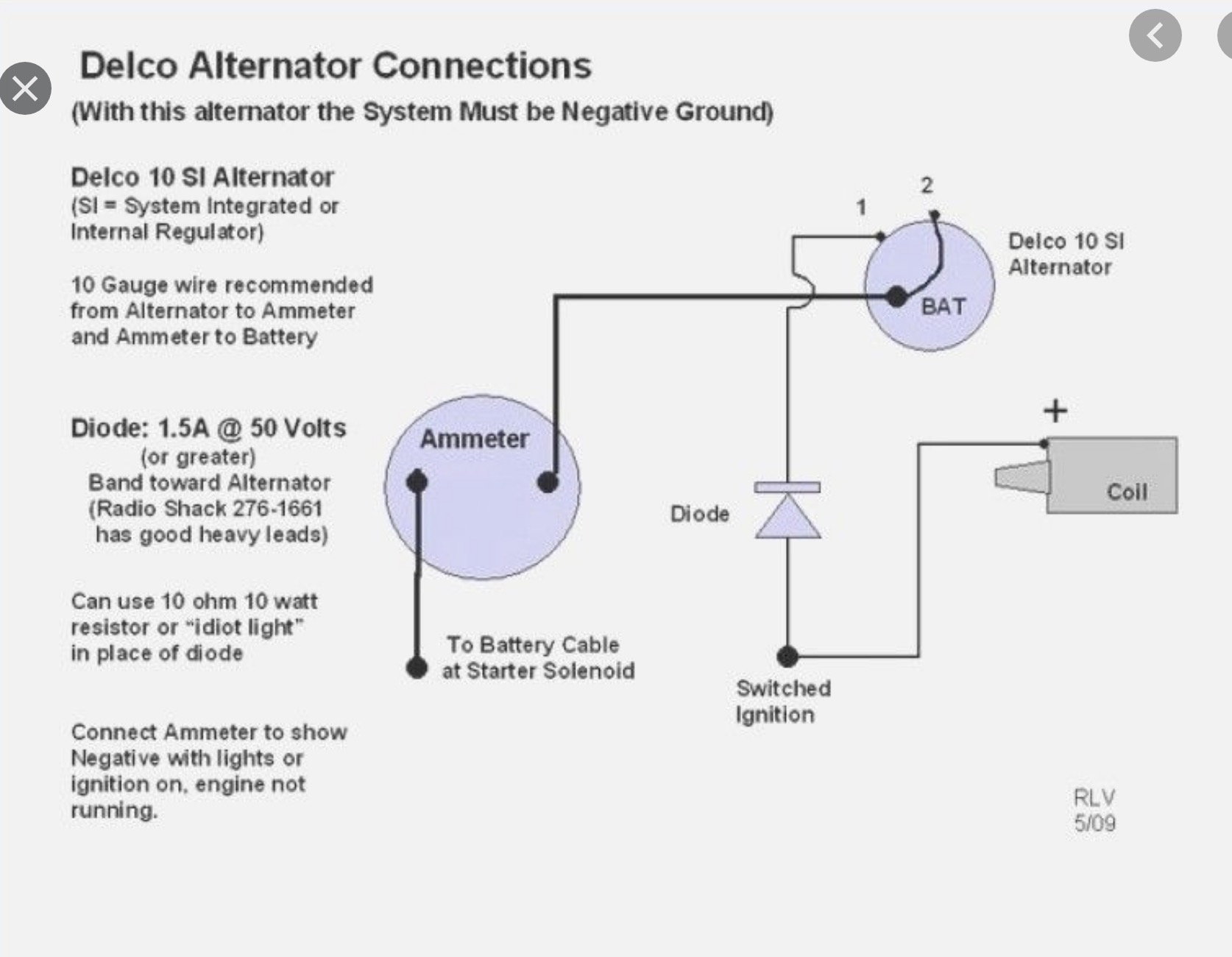
18306 alternator wiring diagram. You may be able to know precisely if the tasks ought to be accomplished, which makes it much easier for you to correctly control your time and. This system is unregulated in that the energy delivered to the battery is totally dependent on engine speed • a red wire with a diode and black wire without a diode is a dual circuit system that offers dc for battery charging and Oct 24, · gahi's diagram is the correct way to wire a gm 10si/12si, and utilize all the benefits of that great.
If you are able to look at a manufacturer's diagram of the alternator's connectors, the wire that slides over pin 1 of the alternator leads to the positive (+) connection on the vehicle's battery and senses voltage. Wiring instructions gm si alternator (one wire or oe hookup) tech dept. It represents the physical parts of the electrical circuit as geometric forms, with the real power and connection connections in between them as thin sides.
Difference in wiring compared to standard alternators. The alternator is a 3 wire spec'd for a 85 gmc pickup & yes, i got the short harness along with it. Connect alternator to balmar regulator wiring harness as indicated in wiring diagram included on page 12.
It’s supposed to assist all the typical user in developing a suitable method. Most modules use an internal driver to turn the alternator’s field circuit on. 12 volt alternator installation operation manual introduction thank you for choosing a balmarr high output alternator.
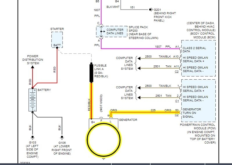
If a new regulator is being installed along with the. Dependin g upon the maximum output of the alternator, use the. You must verify that all required connections are connected to the proper terminal and have the correct voltage in order for the alternator to operate properly.
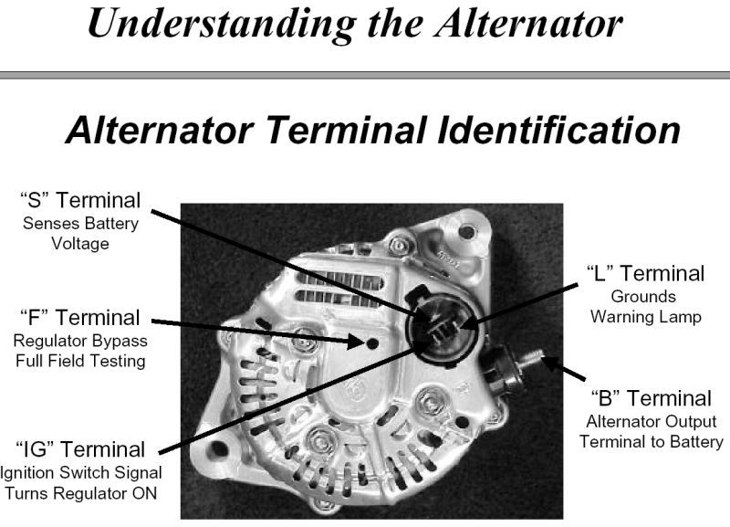
Wiring diagram arrives with several easy to stick to wiring diagram directions. • ig is the ignition input that turns on the alternator/regulator assembly. Your powermaster alternator is designed to work as a 1 wire without any connections to the plug in.
Now, i'm fairly literate in things mechanical but all the wiring diagrams i've seen aren't clear to me. Some shimming or modification to the alternator mount may be required to assure proper alignment. While this series of unit often runs as a self exciting one wire, agricultural applications also used 3 wire connections to the alternator.
This voltage down the exciter wire to the alternator. (tach) wire if needed and other necessary wiring. 21 exciter wire battery light key switch to battery as mentioned before we need the correct voltage at the alternator for it to operate properly.
I got a smoking deal on a 3 wire alternator from rock auto to install in my 62 champ. These guidelines will likely be easy to grasp and apply. If the voltage rises above or falls below 12 volts, the alternator's internal voltage increases or reduces power output to.
By david smith sep 22, 2016. • a single wire with a diode is generally a dc only system. Each part ought to be set and connected with different parts in particular manner.
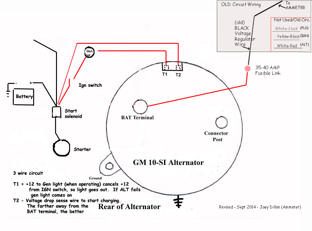
Common delco si series alternator wiring diagram. Many alternators require ignition voltage to initiate charging. If not, the structure will not function as it ought to be.
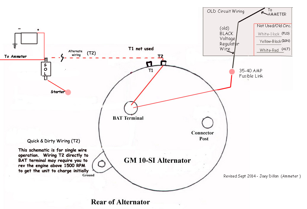
Furthermore, wiring diagram provides you with enough time body in which the assignments are for being completed. Begin by removing the (batt) wire, from the old voltage regulator (or cutout) and connect it to the (10/32) stud on the back of the alternator. Alternators that have one positive wire connected to the alternator has the ground connected to its case.
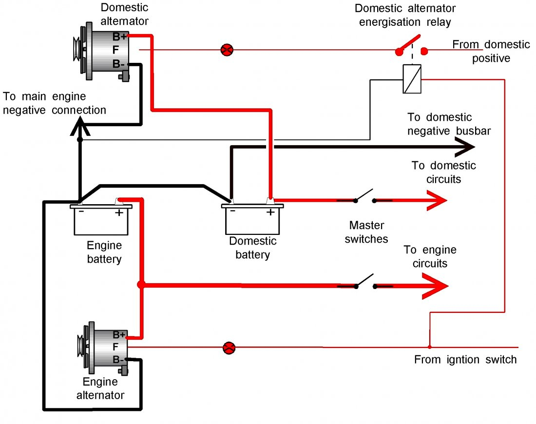
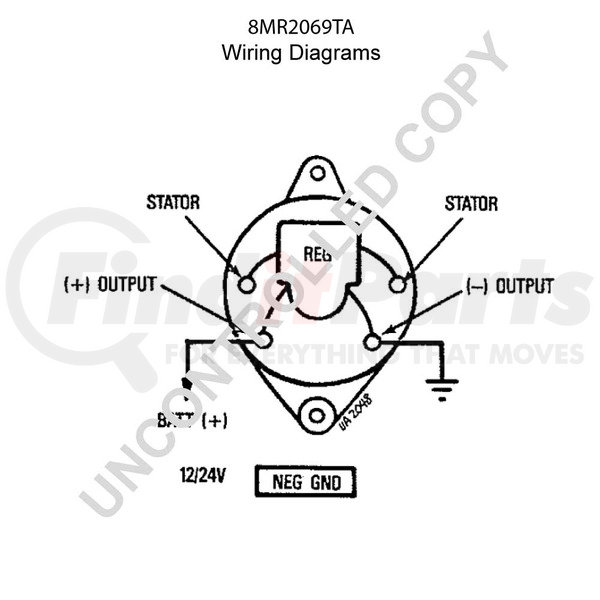
The alternator’s positive and ground cables should be sized according to the chart on page 3. Understanding the alternator • four wires connect the alternator to the rest of the charging system. Alternator wiring diagram wiring diagram is the visual representation of a intricate electric circuit.
Connect alternator to balmar regulator wiring harness as indicated in wiring diagram included on page 12. Below you will find the most common alternator circuits used on marine applications. The alternator has a rotor that spins when the engine cranks.
3 wire alternator wiring diagram source: And connect the red wire to the output side of the alternator 10/32 stud, take the long wire and connect to the + side of the coil. Wiring diagram how an alternator works.
Be sure not to connect the balmar alternator on the ground at any part of the system because it will be not ground isolated anymore! Connect alternator to balmar regulator wiring harness as. Below given are some alternator wiring diagrams that are used for different purposes.let’s have a look at their connections.
Each part ought to be placed and linked to other parts in particular way. The wiring (for maximal 5 metres) should be (150/3) 50mm². The major difference between wiring a series 6 balmar alternators and a regular alternator which is
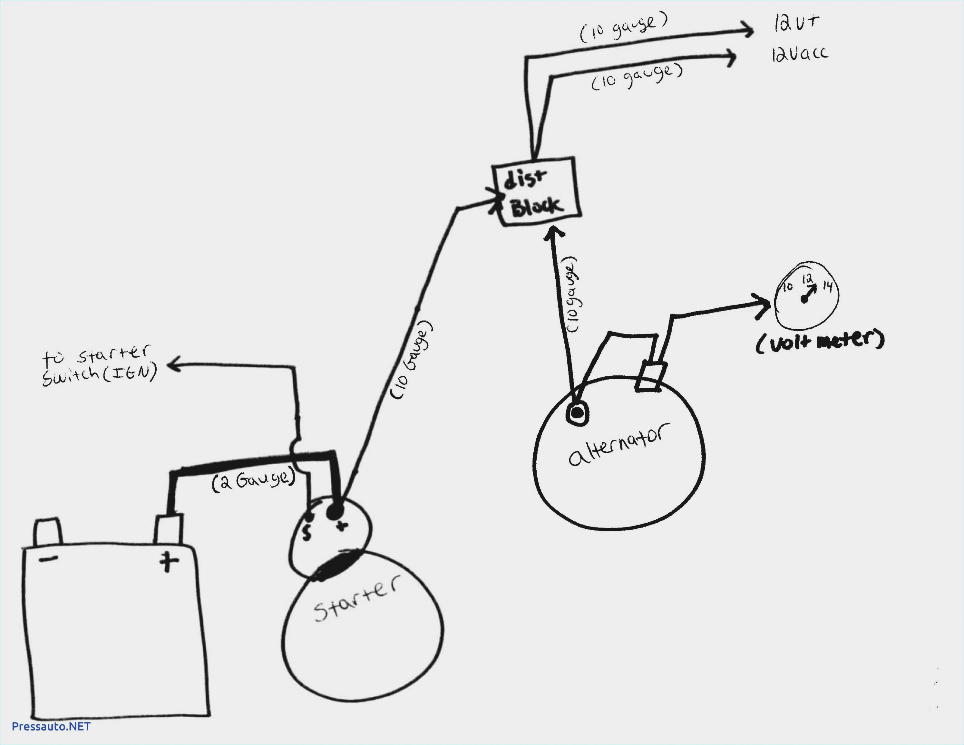
• s is used by the regulator to monitor charging voltage at the battery. This will be the 10 gauge, wire that connects through the amp gauge in the dash. A wire size too small can allow the wire to overheat, melt the insulation and cause a fire or worse.
Alt wire diagram alternator wiring and out the dash warning light 12 volt alternator wiring diagram. How do i wire my marine alternator? Connect the output cable (see cable sizing recommendations below) ground, field wire, stator (tach) wire if needed and other necessary wiring.
Otherwise, the structure won’t function as it should be. We are commonly asked how to wire the delco si series alternators upon maintenance or upgrading from an older generator.
Mf 231 Tractor Wiring Diagram Alternator

Old Gm Alternator Wiring Diagram Has A F And An R
One Wire Alternator Conversion Wiring Diagram Wiring Forums

Alternator wiring

Delcotron Alternator Wiring Diagram Wiring Forums

Alternator Wiring Diagram B D W

Alternator Upgrade Wiring Diagram

Chevy 3 Wire Alternator Diagram

Help!! Anyone know how to set up an alternator light?
Delco 10si Alternator Wiring Diagram
Alternator Wiring SI10
Leece Neville Alternator Wiring Diagram CINTAJUMIESHAHRIL
Gm 1 Wire Alternator Wiring Diagram Cadician's Blog
Basic 12 Volt Alternator Wiring Diagram NZALALA
Nikko Alternator Wiring Diagram

Gm Internal Regulator Alternator Wiring Diagram Wiring Forums

Wiring for alternator with internal regulator CorvetteForum Chevrolet Corvette Forum Discussion
Alternator Wiring Diagram My Son and His Friend Did An Remove and...
1 Wire Alternator Wiring Diagram Wiring Forums in 2021 8n ford tractor, Alternator, Ford
