Dual Ballast Wiring Diagram
Bypassing or removing dual ballast resistor? Compact fluorescent ballast wiring diagram.
Ballast Resistor Question
.jpg)
A wiring diagram is a streamlined traditional pictorial representation of an electric circuit.

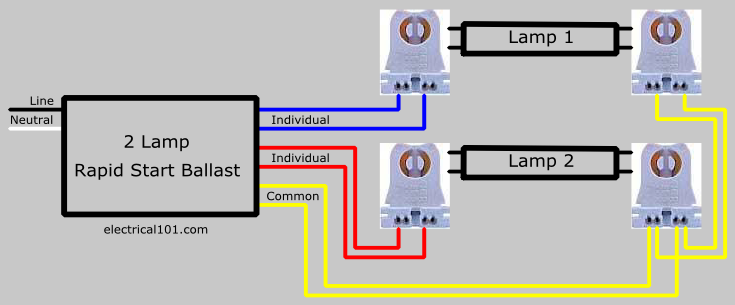
Dual ballast wiring diagram. 100 amp manual transfer switch wiring diagram. Rapid start ballasts 2 lamps. Cut all wires connected to the ballast as shown below and remove ballast as shown in diagrams a, b and c on page 1;
Color coded connectors simplifies wiring se dual entry connectors accessible from bottom or side lamp type 3 way ballast kit offers multiple mounting configurations ultra system limited warranty one year ge lamp and five year ballast electronic ballasts for compact fluorescent and short t5 lamps performance features. Converting fluorescent light fixtures from t12 to t8 bulbs. Ballast resistor wiring diagram points.
4 lamps on a 2 to 1 ballast conversion electrical diy chatroom. To aid in locating specific diagrams, each has been bookmarked and categorized in the navigation window. Resistance varies depending on which one and application, between 1.5 and.25 ohms
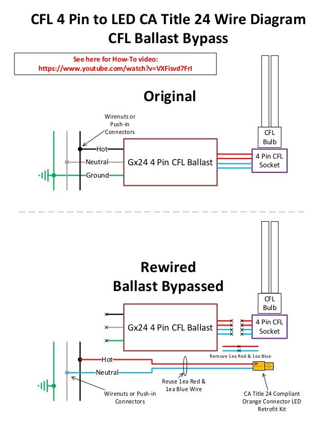
07/12/2021 · what is tube light. Cut the wires from the ballast. 67dart273 fabo gold member fabo gold member.
It includes guidelines and diagrams for various kinds of wiring strategies along with other things like lights, home windows, and so on. Electricians usually refer to a light bulb as a lamp. 4 bulb fluorescent light fixture wiring schematic diagram.
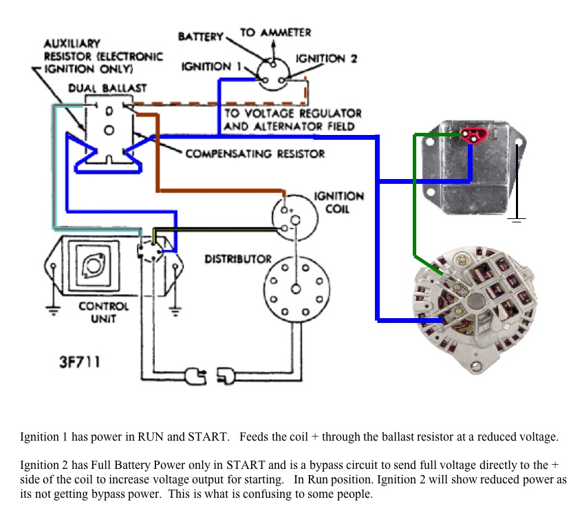
In simple terms the ballast resistor in a mopar limits the amperage or current flow through the coil while the engine is running thereby extending the life of the coil and breaker points of. Metal halide ballasts from keystone include probe and pulse start metal halide 50w through w, including dual tap, quad tap, and 5 tap options. Converting a fixture from a t12 ballast to a t8 ballast.
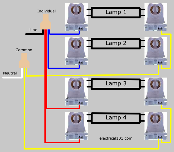
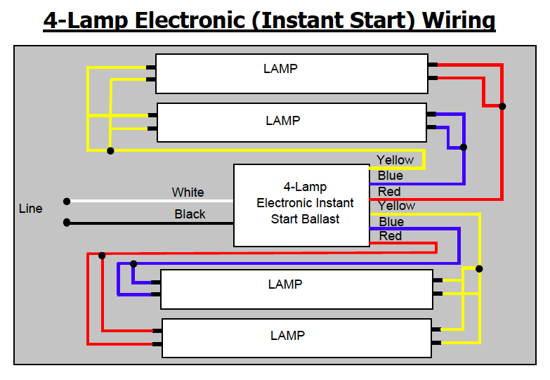
Trim wires to about 1/2” for neutral and 5/8” to 3/4” for line. On the 4 lamp instant start ballast diagram below, each individual wire is connected to a pair of individual wires on the lampholders. The pink (i2) wire only supplies voltage to the coil when the key is in the start position (bypassing the ballast resistor during start).
Ballast” diagram may not necessarily take you to another “two lamp ballast” diagram. Changing the wiring on a fluorescent light fixture from rapid start to instant start, involves changing the wiring from series to parallel. It is the ignition switch engine run wire.
40w electronic ballast circuit diagram. T8 fluorescent lamps vs led s premier lighting. 1000 watt metal halide ballast wiring diagram.
According to the wiring diagram i have it goes to the ignition switch. Line on diagram going to grey has a symbol for a switch and letters sw next to symbol. Remove the ballast from the fixture (or leave it in place).
Wiring diagram consists of numerous detailed illustrations that show the relationship of varied products. Cut the wires from the ballast. Assuming your wiring is the same the wiring is as follows.
Also my ignition wiring to the coil has seen better days i have an orange ecu with matching dual ballast resistor and coil, does anyone have a wiring diagram of the ignition circuit with a duel ballast and the staring bypass. Remove lens and wiring compartment if applicable; Ac input ballast fluorescent lamp fluorescent lam leo amp leo ac input led tube led tube led tube led tube ac input ballast fluorescent lamp fluorescent lamp non.
Trim wires to about 1/2” for neutral and 5/8” to 3/4” for line. Electronic ballast for fluorescent lamp with oscillator clocking a dual mosfet lamp circuit and a voltage regulated dc. Each component ought to be placed and connected with other parts in specific way.
4 bulb ballast wiring diagram 4 lamp t12 ballast 4 lamp emergency ballast wiring diagram wiring diagram manual barbie games co. One is 5 ohms ( secondary ) which feeds the stock 5 pins ecu, and the other one is anything between 1.5 or.5 ohms ( primary ) which feeds the coil. Get electronic ballast wiring diagram background.
Ad find deals on products in ballasts on amazon. Follow the wiring diagram that came with your new ballast. Electronic ballast for fluorescent lamp with oscillator clocking a dual mosfet lamp circuit and a voltage regulated dc.
Instant start ballasts can only be wired in parallel according to the diagram on the ballast. T12 to t8 ballast wiring diagram wiring diagram is a simplified gratifying pictorial representation of an electrical circuit it shows the components of the circuit as simplified shapes and the knack and signal associates in the midst of the devices. Installation wiring diagrams single ended vs.
Looking at the ballast wiring diagram, black, white, and grey wires to orange quick disconnect. Rapid start ballasts can only be wired in series according to the diagram on the ballast. Instructions for single ended wiring installation removing existing fluorescent system 1.
Double ended ballast bypass rewiring matrix. Ge 2 bulb residential electronic fluorescent light ballast at. Using tan wire connector for line and orange wire connector for neutral.
Us standards are black is hot white is neutral green is ground or just a solid copper wire. You should be connecting to the red wire (i1) from the ignition switch. 1008 prudential reserves the right to change design specifications or materials without notice.
Similar sized wire connectors can be used. Single ballast just provides power for the coil. Remove the ballast from the fixture (or leave it in place).
Dual ballast provides two sources by two diff resistances. Using tan wire connector for line and orange wire connector for neutral. T8 ballast wiring diagram in 2021 led fluorescent tube led tubes led tube light.
If you know the actual model number of the ac ballast that the emergency. This ballast has about twice as many wires to connect as my old fixture. 4 lamp t5 ballast wiring diagram lovely wiring diagram for.
Two individual wires of the same color (blue or red) connect to each of the individual pairs on lamps 1 and 4. A657 347 volt hid ballast wiring diagram. Cut all the wires that are keeping the ballast in the fixture within 2 inches of length.
2) using the find command some diagrams feature a model list for reference.
Charger Electronic ignition wiring Mopar Forums
Wiring Diagram Info 35 Emergency Ballast Wiring Diagram
4 Lamp T5 Ballast Wiring Diagram schematic and wiring diagram
Osram Led Tube Wiring Diagram
Dual Headlamp Relay Wiring Diagram

DirectWire SingleEnded LED Tube Lights Electrical 101

Wiring Diagram For 1000w Pulse Start Metal Halide Ballast
Get Icn 4p32 N Wiring Diagram Sample

DirectWire DualEnded LED Tube Lights 4 Lamps Electrical 101
Series Ballast Lampholder Wiring 2 and 4 Lamps Electrical 101
Automotive, Ballast Wiring Diagram Simple Wiring Diagram, Headlights Headlight Relay Dual

Xantec Hid Ballast Wiring Diagram Wiring Diagram Schemas

Bypassing or Removing Dual Ballast Resistor?

4 Ways to Convert a Fluorescent Tubelight with 2 Ballasts to a LED T8 Fixture / Total Lighting Blog
Wiring Diagram For A Brillihood T8
T12 To T8 Ballast Wiring Diagram nuryadiardi
100 Mh Ballast Wiring Diagram
4 Light Ballast Wiring Diagram Wiring Diagram Schemas
Does anyone know of a viable substitue for the 2 restistors in the ignition circuit on a 77 924
